Tuesday, May 31, 2016

Location of ESXi log files


You can review ESXi host log files using these methods:

ESXi Host Log Files

  • /var/log/auth.log: ESXi Shell authentication success and failure.
  • /var/log/dhclient.log: DHCP client service, including discovery, address lease requests and renewals.
  • /var/log/esxupdate.log: ESXi patch and update installation logs.
  • /var/log/lacp.log: Link Aggregation Control Protocol logs.
  • /var/log/hostd.log: Host management service logs, including virtual machine and host Task and Events, communication with the vSphere Client and vCenter Server vpxa agent, and SDK connections.
  • /var/log/hostd-probe.log: Host management service responsiveness checker.
  • /var/log/rhttpproxy.log: HTTP connections proxied on behalf of other ESXi host webservices.
  • /var/log/shell.log: ESXi Shell usage logs, including enable/disable and every command entered. For more information, see vSphere 5.5 Command-Line Documentation and Auditing ESXi Shell logins and commands in ESXi 5.x (2004810).
  • /var/log/sysboot.log: Early VMkernel startup and module loading.
  • /var/log/boot.gz: A compressed file that contains boot log information and can be read using zcat /var/log/boot.gz|more.
  • /var/log/syslog.log: Management service initialization, watchdogs, scheduled tasks and DCUI use.
  • /var/log/usb.log: USB device arbitration events, such as discovery and pass-through to virtual machines.
  • /var/log/vobd.log: VMkernel Observation events, similar to vob.component.event.
  • /var/log/vmkernel.log: Core VMkernel logs, including device discovery, storage and networking device and driver events, and virtual machine startup.
  • /var/log/vmkwarning.log: A summary of Warning and Alert log messages excerpted from the VMkernel logs.
  • /var/log/vmksummary.log: A summary of ESXi host startup and shutdown, and an hourly heartbeat with uptime, number of virtual machines running, and service resource consumption. For more information, see Format of the ESXi 5.0 vmksummary log file (2004566).
  • /var/log/Xorg.log: Video acceleration.
Note: For information on sending logs to another location (such as a datastore or remote syslog server), see Configuring syslog on ESXi 5.0 (2003322).

Logs from vCenter Server Components

When an ESXi 5.1 / 5.5 host is managed by vCenter Server 5.1 and 5.5, two components are installed, each with its own logs:
  • /var/log/vpxa.log: vCenter Server vpxa agent logs, including communication with vCenter Server and the Host Management hostd agent.
  • /var/log/fdm.log: vSphere High Availability logs, produced by the fdm service. For more information, see the vSphere HA Security section of the vSphere Availability Guide.

Wednesday, May 25, 2016

VMware Appliance Default Passwords


VMware appliances I use with their default username and password.


VMware vCloud Director 5.1.1 Appliance
username: root
password: vmware

VMware vCloud Director Appliance/Oracle Database 11g R2 XE instance
username: vcloud
password: VCloud

vCloud Director Web based Login
https://<ip-address>/cloud/
username: administrator
password: specified during wizard setup

vCloud Connector Server
https://<ip-address>:5480
username: admin
password: vmware

vCloud Connector Node
https://<ip-adress>:5480
username: admin
password: vmware

vCenter Appliance Configuration
https://<ip-address>:5480
username: root
password: vmware

vCenter Application Discovery Manager
http://<ip-address>
username: root
password: 123456

vCenter Web Client Configuration
https://<ip-address>:9443/admin-app
username: root
password: vmware

vCenter vSphere Web Client Access
https://<ip-adress>:9443/vsphere-client/
username: root
password: vmware

vCenter Single Sign On (SSO)
https://<ip-address>:7444/lookupservice/sdk
Windows default username: admin@System-Domain
Linux (Virtual Appliance) default username: root@System-Domain
password: specified during installation

vCenter Operations
UI Manager: https://<ip-address>
username: admin
password: admin
Admin: https://<ip-address>/admin
username: admin
password: admin
Custom UI: https://<ip-address>/vcops-custom/
username: admin
password: admin

VMware Site Recovery Manager
username: vCenter administrator username
password: vCenter administrator password

vShield Manager
username: admin
password: default
type “enable”
password: default
type “setup” then configure IP settings
http://<ip-address>

vSphere Management Assistant (vMA)
username: vi-admin
password: <defined during configuration>

vSphere Data Recovery Appliance
username = root
password = vmw@re

VMware vCenter Application Discovery Manager
The default ADM management console password is 123456 and the CLI password is ChangeMe

Monday, May 23, 2016

VSAN 6.0 Fault Domains


One of the really nice new features of VSAN 6.0 is fault domains. Previously, there was very little control over where VSAN placed virtual machine components. In order to protect against something like a rack failure, you may have had to use a very high NumberOfFailuresToTolerate value, resulting in multiple copies of the VM data dispersed around the cluster. With VSAN 6.0, this is no longer a concern as hosts participating in the VSAN Cluster can be placed in different failure domains. This means that component placement will take place across failure domains and not just across hosts. Let’s look at this in action.
In this example, I have a 4 node cluster. I am going to create 3 default domains. The first fault domain contains one host, the second fault domain also contains one host, and the third fault domain has two hosts. It looks something like this:

Of course, this isn’t a very realistic setup, as you would typically have many more hosts per rack, but this is what I had at my disposal to test this feature. However, the concept remains the same. The idea now is to have VSAN deploy virtual machine components across the fault domains in such a way so as a single rack failure will not make the VM inaccessible, in order words maintain a full copy of the virtual machine data even when a rack fails.
The first step is to setup the fault domains. This is done in the vSphere web client under Settings > Virtual SAN > Fault Domains:

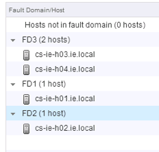
Using the green + symbol, fault domains with hosts can be created. Based on the design outlined above, I ended up with a fault domain configuration looking like this:
A5Now in my configuration, each hosts has 2 magnetic disks (HDDs) so I decided that in order to use as much of the hardware as possible, I would create a VM Storage Policy with StripeWidth (NumberOfDiskStripesPerObject) = 3 and FTT (NumberOfFailuresToTolerate) = 1. I then deployed a virtual machine with this policy. I then examined the policy after the VM was deployed. First I made sure that the VM was compliant to the policy, in other words VSAN was able to meet the StripeWidth and FTT requirements in the policy, which it was (VM > Manage > Policies):

I then checked the placement of the components using the VM > Monitor > Policies view:

As we can see, one copy of the data (RAID 0, 3 way stripe) resides on host 1 and 2, and the other copy of the data (RAID 0, 3 way stripe) resides on hosts 3 and 4. Both are mirrored/replicated in a RAID 1 configuration. Now, these are the questions we need to ask ourselves:
  •  If rack 1 fails (containing host 1), do I still have a full copy of the data? The answer is Yes.
  •  If rack 2 fails (containing host 2), do I still have a full copy of the data? The answer is Yes.
  •  If rack 3 fails (containing hosts 3 & 4), do I still have a full copy of the data? The answer is still Yes.
What about quorum if rack 3 fails? There are no witnesses present in this configuration, so how is quorum achieved? Well this is another new enhancement in VSAN 6.0 whereby, under certain conditions, components can have votes rather than rely on witnesses. 
Fault domains, a nice new addition to Virtual SAN 6.0. Previously with FTT, we stated that you needed ‘2n + 1’ hosts to tolerate ‘n’ failures. With fault domains, you now need ‘2n + 1’ fault domains to tolerate ‘n’ failures.

VMware’s Software FCoE (Fibre Channel over Ethernet) Adapter

Posted on December 7, 2011 by 

The FCoE protocol encapsulates Fibre Channel frames into Ethernet frames. As a result, your host can use 10 Gbit lossless Ethernet to deliver Fibre Channel traffic. The lossless part is important and I'll return to that later.
Configuration Steps
A Software FCoE Adapter is software code that performs some of the FCoE processing. The adapter can be used with a number of NICs that support partial FCoE offload. Unlike the hardware FCoE adapter, the software adapter needs to be activated on an ESXi 5.0, similar to how the Software iSCSI adapter is enabled. Go to Storage Adapters in the vSphere client and click 'Add':
Picture1
To use the Software FCoE Adapter, the NIC used for FCoE must be bound as an uplink to a vSwitch  which contains a VMkernel portgroup (vmk). Since FCoE packets are exchanged in a VLAN, the VLAN ID must be set on the physical switch to which the adapter is connected, not on the adapter itself. The VLAN ID is automatically discovered during the FCoE Initialization Protocol (FIP) VLAN discovery process so there is no need to set the VLAN ID manually.
Picture2

Enhancing Standard Ethernet to handle FCoE
For Fiber Channel to work over Ethernet, there are a number of criteria which must be addressed, namely handling losslessness/congestion and bandwidth management.
1. Losslessness & Congestion: Fiber Channel is a lossless protocol, so no frames can be lost. Since classic Ethernet has no flow control, unlike Fibre Channel, FCoE requires enhancements to the Ethernet standard to support a flow control mechanism to prevents frame loss. One of the problems with Ethernet networks is that when a congestion condition arises, packets will be dropped (lost) if there is no adequate flow control mechanism. A flow control method that is similar to the buffer to buffer credit method on Fiber Channel is needed for FCoE.
FCoE uses a flow control PAUSE mechanism, similar to buffer-to-buffer credits in FC, to ask a transmitting device to hold off sending any more frames until the receiving device says its ok to resume. However, the PAUSE mechanism is not intelligent and could possibly pause all traffic, not just FCoE traffic. To overcome this, the quality of service (QoS) priority bit in the VLAN tag of the Ethernet frame is used to differentiate the traffic types on the network. Ethernet can now be thought of as being divided into 8 virtual lanes based on the QoS priority bit in the VLAN tag.
Picture3
Different policies such as losslessness, bandwidth allocation and congestion control can be applied these virtual lanes individually. If congestion arises and there is a need to ‘pause’ the Fiber Channel traffic (i.e. the target is busy processing, and wants the source to hold off sending any more frames), then there must be a way of pausing the FC traffic without impacting other network traffic using the wire. Let’s say that FCoE, VM traffic, VMotion traffic, management traffic & FT traffic are all sharing the same 10Gb pipe. If we have congestion with FCoE, we may want to pause it. However, we don’t want to pause all traffic, just FCoE. With standard ethernet, this is not possible – you have to pause everything. So we need an enhancement to pause one class of traffic while allowing the rest of the traffic to flow. PFC (Priority based Flow Control) is an extension of the current Ethernet pause mechanism, sometimes called Per-Priority PAUSE. using per priority pause frames. This way we can pause traffic with a specific priority and allow all other traffic to flow (e.g. pause FCoE traffic while allowing other network traffic to flow).
2. Bandwidth: there needs to be a mechanism to reduce or increase bandwidth. Again, with a 10Gb pipe, we want to be able to use as much of the pipe as possible when other traffic classes are idle. For instance, if we’ve allocated 1Gb of the 10Gb pipe for vMotion traffic, we want this to be available to other traffic types when there are no vMotion operations going on, and similarly we want to dedicate it to vMotion traffic when there are vMotions. Again, this is not achievable with standard ethernet so we need some way of implementing this. ETS (Enhanced Transmission Selection) provides a means to allocate bandwidth to traffic that has a particular priority. The protocol supports changing the bandwidth dynamically.
DCBX – Data Center Bridging Exchange
Data Center Bridging Exchange (DCBX) is a protocol that allows devices to discover & exchange their capabilities with other attached devices. This protocol ensures a consistent configuration across the network. The three purposes of DCBX are:
 
  1. Discover Capabilities: The ability for devices to discover and identify capabilities of other devices.  
  2. Identify misconfigurations: The ability to discover misconfigurations of features between devices.  Some features can be configured differently on each end of a link whilst other features must be configured identically on both sides. This functionality allows detection of configuration errors. 
  3. Configuration of Peers: A capability allowing DCBX to pass configuration information to a peer.
DCBX relies on Link Layer Discovery Protocol (LLDP) in order to pass this configuration information. LLDP is an industry standard version of Cisco Discovery Protocol (CDP) which allows devices to discover one another and exchange information about basic capabilities. This is why we need to bind a VMkernel port to a vSwitch.  Frames will be forwarded to the userworld dcdb process via the CDP VMkernel module to do DCBX. The CDP VMkernel module does both CDP & LLDP. This is an important point to note – the FCoE traffic does not go through the vSwitch. However we need the vSwitch binding so that the frames will be forwarded to the dcbd in userworld through the CDP VMkernel module for DCBx negotiation.  The vSwitch is NOT for FCoE data traffic.
Once the Software FCoE is enabled, a new adapter is created, and discovery of devices can now take place.
Picture4

References:
  • Priority Flow Control (PFC) – IEEE 802.1Qbb – Enable multiple traffic types to share a common Ethernet link without interfering with each other
  • Enhanced Transmission Selection (ETS) – IEEE 802.1Qaz – Enable consistent management of QoS at the network level by providing consistent scheduling
  • Data Center Bridging Exchange Protocol (DCBX) – IEEE 802.1Qaz – Management protocol for enhanced Ethernet capabilities
  • VLAN tag – IEEE 802.1q
  • Priority tag – IEEE 802.1p

Troubleshooting
The software FCoE adapter can be troubleshooted using a number of techniques available in ESXi 5.0. First there is theesxcli fcoe command namespace that can be used to get adapter & nic information:
Esxcli-fcoe
The dcbd daemon on the ESXi host will record any errors with discovery or communication. This daemon logs to/var/log/syslog.log. For increased verbosity, dcdb can be run with a '-v' option. There is also a proc node created when the software FCoE adapter is created, and this can be found in /proc/scsi/fcoe/<instance>. This contains interesting information about the FCoE devices discovered, and this proc node should probably be the starting point for an FCoE troubleshooting. Another useful utility is ethtool. When this command is run with the '-S' option against a physical NIC, it will display statistics including fcoe errors & dropped frames. Very useful.

Sunday, May 22, 2016

ESXi Passwords and Account Lockout

For ESXi hosts, you have to use a password with predefined requirements. You can change the required length and character class requirement or allow pass phrases using the Security.PasswordQualityControl advanced option.
ESXi uses the Linux PAM module pam_passwdqc for password management and control. See the manpages for pam_passwdqc for detailed information.
ESXi enforces password requirements for direct access from the Direct Console User Interface, the ESXi Shell, SSH, or the vSphere Client. When you create a password, include a mix of characters from four character classes: lowercase letters, uppercase letters, numbers, and special characters such as underscore or dash.
Note
An uppercase character that begins a password does not count toward the number of character classes used. A number that ends a password does not count toward the number of character classes used.
The password cannot contain a dictionary word or part of a dictionary word.
The following password candidates illustrate potential passwords if the option is set to
retry=3 min=disabled,disabled,disabled,7,7
That means that passwords with one or two character classes and pass phases are not allowed, as indicated by the first three disabled items. Passwords from three and four character classes require seven characters. See the manpages for pam_passwdqc for detailed information.
The following passwords are allowed.
xQaTEhb!: Contains eight characters from three character classes.
xQaT3#A: Contains seven characters from four character classes.
The following password candidates do not meet ESXi requirements.
Xqat3h?: Begins with an uppercase character, reducing the effective number of character classes to two. The minimum number of supported character classes is three.
xQaTEh2: Ends with a number, reducing the effective number of character classes to two. The minimum number of supported character classes is three.
Instead of a password, you can also use a pass phrase, however, pass phrases are disabled by default. You can change this default or other settings, by using the Security.PasswordQualityControl advanced option for your ESXi host from the vSphere Web Client.
For example, you can change the option to the following:
retry=3 min=disabled,disabled,16,7,7
This example allows pass phrases of at least 16 characters and at least 3 words, separated by spaces.
Making changes to the /etc/pamd/passwd file is still supported for legacy hosts but is deprecated for future releases.
You can change the default restriction on passwords or pass phrases by using the Security.PasswordQualityControl advanced option for your ESXi host. By default, this option is set as follows:
retry=3 min=disabled,disabled,disabled,7,7
You can change the default, for example, to require a minimum of 15 characters and a minimum number of four words, as follows:
retry=3 min=disabled,disabled,15,7,7 passphrase=4
See the manpage for pam_passwdqc for more information.
Note
Not all possible combinations of the options for pam_passwdqc have been tested. Perform additional testing after you make changes to the default password settings.
See the vCenter Server and Host Management documentation for information on setting ESXi advanced options.
Starting with vSphere 6.0, account locking is supported for access through SSH and through the vSphere Web Services SDK. The Direct Console Interface (DCUI) and the ESXi Shell do not support account lockout. By default, a maximum of ten failed attempts is allowed before the account is locked. The account is unlocked after two minutes by default.
You can configure the login behavior with the following advanced options:
Security.AccountLockFailures. Maximum number of failed login attempts before a user's account is locked. Zero disables account locking.
Security.AccountUnlockTime. Number of seconds that a user is locked out.
See the vCenter Server and Host Management documentation for information on setting advanced options.