On A Cisco switch , you can display the CAM or MAC address table with the
following commands:


  SW1#show mac ad
SW1#show mac address-table ?
  address       Address to lookup in the table
  aging-time    MAC address table aging parameters
  count         Number of MAC addresses in the table
  dynamic       List dynamic MAC addresses
  interface     List MAC adresses on a specific interface
  learning      Display learning on VLAN or interface
  move          MAC Move information
  multicast     List multicast MAC addresses
  notification  MAC notification parameters and history table
  secure        List secure MAC addresses
  static        List static MAC addresses
  vlan          List MAC addresses on a specific vlan
  |             Output modifiers


dddd


ddd

d
Thursday, October 6, 2016
Displaying the MAC address table (CAM) on Cisco Switch
Tuesday, October 4, 2016
Verifying the CIsco StackPower status
I have 2 Cisco WS-C3750X-12S-E stacked and want to check the status of the StackPower.
Here are some switch StackPower validation commands:
sh stack-power
sh stack-power detail
sh stack-power neighbor
Here are some switch StackPower validation commands:
sh stack-power
sh stack-power detail
sh stack-power neighbor
Verifying the CIsco Stackwise stack status
I have 2 Cisco WS-C3750X-12S-E stacked and want to check the status of the stack.
Here are some switch stack validation commands:
sh switch
sh switch detail
sh switch neighbor
sh switch stack-ring speed
sh switch stack-ring activity
sh switch stack-port
sh switch stack-port sum
Here are some switch stack validation commands:
sh switch
sh switch detail
sh switch neighbor
sh switch stack-ring speed
sh switch stack-ring activity
sh switch stack-port
sh switch stack-port sum
Thursday, September 22, 2016
Enabling and Disabling Cisco StackWise and StackPower ports
Enabling/Disabling Stack Power ports on Cisco 3750
3750X#sh stack-power neighbors
Power Stack Stack Stack Total Rsvd Alloc Unused Num Num
Name Mode Topolgy Pwr(W) Pwr(W) Pwr(W) Pwr(W) SW PS
-------------------- ------ ------- ------ ------ ------ ------ --- ---
Powerstack-1 SP-PS Stndaln 350 120 230 0 1 1
Powerstack-2 SP-PS Stndaln 350 120 230 0 1 1
Power Stack Port 1 Port 1 Port 2 Port 2
SW Name Status Neighbor SW:MAC Status Neighbor SW:MAC
-- -------------------- ------ ---------------- ------ ----------------
1 Powerstack-1 NoConn - NoConn -
2 Powerstack-2 Shut - Shut -
3750X#stack-power switch 2 port 2 enable
3750X#stack-power switch 2 port 1 enable
000151: *Jan 1 15:14:45.791 HST: %PLATFORM_STACKPOWER-6-CABLE_EVENT: Switch 1
stack power cable 2 inserted
000152: *Jan 1 15:14:46.370 HST: %PLATFORM_STACKPOWER-6-CABLE_EVENT: Switch 2 stack power cable 1 inserted
3750X#sh stack-power neighbors
Power Stack Stack Stack Total Rsvd Alloc Unused Num Num
Name Mode Topolgy Pwr(W) Pwr(W) Pwr(W) Pwr(W) SW PS
-------------------- ------ ------- ------ ------ ------ ------ --- ---
Powerstack-1 SP-PS Ring 700 470 460 -230 2 2
Powerstack-2 SP-PS Ring 700 470 460 -230 2 2
Power Stack Port 1 Port 1 Port 2 Port 2
SW Name Status Neighbor SW:MAC Status Neighbor SW:MAC
-- -------------------- ------ ---------------- ------ ----------------
1 Powerstack-1 Conn 2:bc16.6550.a600 Conn 2:bc16.6550.a600
2 Powerstack-2 Conn 1:30f7.0d41.d100 Conn 1:30f7.0d41.d100
Notice the Stack topology is now in RING state:
330-OP0-1-CR1#sh stack-power detail
Power Stack Stack Stack Total Rsvd Alloc Unused Num Num
Name Mode Topolgy Pwr(W) Pwr(W) Pwr(W) Pwr(W) SW PS
-------------------- ------ ------- ------ ------ ------ ------ --- ---
Powerstack-1 SP-PS Ring 700 240 460 0 2 2
Power stack name: Powerstack-1
Stack mode: Power sharing
Stack topology: Ring
Switch 1:
Power budget: 230
Power allocated: 230
Low port priority value: 21
High port priority value: 12
Switch priority value: 3
Port 1 status: Connected
Port 2 status: Connected
Neighbor on port 1: Switch 2 - bc16.6550.a600
Neighbor on port 2: Switch 2 - bc16.6550.a600
Switch 2:
Power budget: 230
Power allocated: 230
Low port priority value: 22
High port priority value: 13
Switch priority value: 4
Port 1 status: Connected
Port 2 status: Connected
Neighbor on port 1: Switch 1 - 30f7.0d41.d100
Neighbor on port 2: Switch 1 - 30f7.0d41.d100
3750X#sh stack-power neighbors
Power Stack Stack Stack Total Rsvd Alloc Unused Num Num
Name Mode Topolgy Pwr(W) Pwr(W) Pwr(W) Pwr(W) SW PS
-------------------- ------ ------- ------ ------ ------ ------ --- ---
Powerstack-1 SP-PS Stndaln 350 120 230 0 1 1
Powerstack-2 SP-PS Stndaln 350 120 230 0 1 1
Power Stack Port 1 Port 1 Port 2 Port 2
SW Name Status Neighbor SW:MAC Status Neighbor SW:MAC
-- -------------------- ------ ---------------- ------ ----------------
1 Powerstack-1 NoConn - NoConn -
2 Powerstack-2 Shut - Shut -
3750X#stack-power switch 2 port 2 enable
3750X#stack-power switch 2 port 1 enable
000151: *Jan 1 15:14:45.791 HST: %PLATFORM_STACKPOWER-6-CABLE_EVENT: Switch 1
stack power cable 2 inserted
000152: *Jan 1 15:14:46.370 HST: %PLATFORM_STACKPOWER-6-CABLE_EVENT: Switch 2 stack power cable 1 inserted
3750X#sh stack-power neighbors
Power Stack Stack Stack Total Rsvd Alloc Unused Num Num
Name Mode Topolgy Pwr(W) Pwr(W) Pwr(W) Pwr(W) SW PS
-------------------- ------ ------- ------ ------ ------ ------ --- ---
Powerstack-1 SP-PS Ring 700 470 460 -230 2 2
Powerstack-2 SP-PS Ring 700 470 460 -230 2 2
Power Stack Port 1 Port 1 Port 2 Port 2
SW Name Status Neighbor SW:MAC Status Neighbor SW:MAC
-- -------------------- ------ ---------------- ------ ----------------
1 Powerstack-1 Conn 2:bc16.6550.a600 Conn 2:bc16.6550.a600
2 Powerstack-2 Conn 1:30f7.0d41.d100 Conn 1:30f7.0d41.d100
Notice the Stack topology is now in RING state:
330-OP0-1-CR1#sh stack-power detail
Power Stack Stack Stack Total Rsvd Alloc Unused Num Num
Name Mode Topolgy Pwr(W) Pwr(W) Pwr(W) Pwr(W) SW PS
-------------------- ------ ------- ------ ------ ------ ------ --- ---
Powerstack-1 SP-PS Ring 700 240 460 0 2 2
Power stack name: Powerstack-1
Stack mode: Power sharing
Stack topology: Ring
Switch 1:
Power budget: 230
Power allocated: 230
Low port priority value: 21
High port priority value: 12
Switch priority value: 3
Port 1 status: Connected
Port 2 status: Connected
Neighbor on port 1: Switch 2 - bc16.6550.a600
Neighbor on port 2: Switch 2 - bc16.6550.a600
Switch 2:
Power budget: 230
Power allocated: 230
Low port priority value: 22
High port priority value: 13
Switch priority value: 4
Port 1 status: Connected
Port 2 status: Connected
Neighbor on port 1: Switch 1 - 30f7.0d41.d100
Neighbor on port 2: Switch 1 - 30f7.0d41.d100
Enabliing/Disabling StackWise ports on Cisco 3750:
3750x#switch 1 stack port 1 enable
Enabling/disabling a stack port may cause undesired stack changes. Continue?[confirm]
3750x#switch 1 stack port 2 enable
Enabling/disabling a stack port may cause undesired stack changes. Continue?[confirm]
3750x#sh switch detail
Switch/Stack Mac Address : 30f7.0d41.d100
H/W Current
Switch# Role Mac Address Priority Version State
----------------------------------------------------------
*1 Master 30f7.0d41.d100 15 3 Ready
2 Member bc16.6550.a600 14 3 Ready
Stack Port Status Neighbors
Switch# Port 1 Port 2 Port 1 Port 2
--------------------------------------------------------
1 Ok Ok 2 2
2 Ok Ok 1 1
3750x#sh switch neighbors
Switch # Port 1 Port 2
-------- ------ ------
1 2 2
2 1 1
3750x#
Thursday, July 14, 2016
Recovering from a Cisco IOS Software Failure via USB
Switch software can be corrupted during an upgrade, by downloading the wrong file to the switch, and by deleting the image file. In all of these cases, the switch does not pass the power-on self-test (POST), and there is no connectivity.
This procedure uses boot loader commands and USB to recover from a corrupted or wrong image file.
This recovery procedure requires that you have physical access to the switch.
Recommend free terminal application are:
Kitty Putty
Tera term 4.91
ExTraPutty
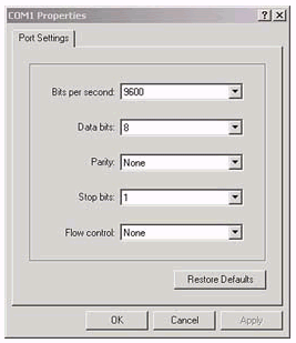
If you have not already done so, connect a PC to the console port of the switch. For information on how to connect a terminal to a Catalyst fixed configuration switch, refer to Connecting a Terminal to the Console Port on Catalyst Switches. Use a terminal emulation program such as Microsoft Windows HyperTerminal in order to establish the console session. These are the settings:
- Bits per second: 9600
- Data bits: 8
- Parity: None
- Stop bits: 1
- Flow control: None
Problem
When Catalyst fixed configuration switches experience boot errors, these conditions can apply:
- The switch is in a continuous reboot.
- The switch displays the switch: prompt.
- The error loading flash: message appears.
Switch Displays the Switch: Prompt or "Error Loading Flash:"
- The switch: prompt indicates that the switch has not booted completely and requires the user to complete the boot process.
- The error loading flash:<image> message indicates that the switch failed to load an image because of a corrupt or missing image.The corrupt or missing image can be the result of a failed download. In this case, the image has a bad checksum or a failed software upgrade, and the upgrade procedure was not followed properly. There is the possibility that the user deleted the image but did not replace the image. A boot variable can have been set incorrectly.
With a console session open, you see an error message that is similar to this:
Error loading "flash:c2950-i6q4l2-mz.121-12c.EA1.bin"
Normally, the switch attempts to automatically boot the next valid image in the Flash file system. Here is an example:
Error loading "flash:c2950-i6q4l2-mz.121-12c.EA1.bin"
Interrupt within 5 seconds to abort boot process.
Loading "flash:/c2950-i6q4l2-mz.121-13.EA1.bin"...######
########################################################

!--- Output suppressed.
If there is no valid backup image from which to boot, the boot process fails completely. Here is an example:
Error loading "flash:c2950-i6q4l2-mz.121-12c.EA1.bin"
Interrupt within 5 seconds to abort boot process.
Boot process failed...
Step-by-Step Recovery Procedure
Use this solution to solve the problem.
Note: A PC must be attached to the console port of the switch, as the Prerequisites section of this document states.
- If the switch is in a continuous reboot, complete one of the procedures in this step, which depends on your switch model.Note: If the switch is not in a continuous reboot, but is already at the switch: prompt, proceed directly to Step 2.
- Catalyst 2940 and 2950 series switches
- Unplug the power cord.
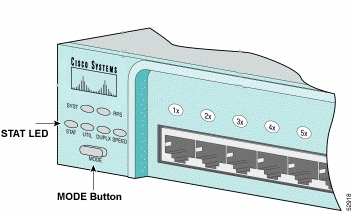
- Hold down the MODE button while you reconnect the power cable to the switch.The MODE button is on the left side of the front panel.
- Release the MODE button after the STAT LED goes out.Note: The LED position can vary slightly, which depends on the model.You are now at the switch: prompt.
- Proceed to Step 2.
- Catalyst 2970, 3550, 3560 and 3750 series switches
- Unplug the power cord.
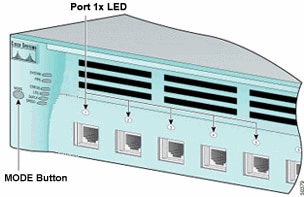
- Hold down the MODE button while you reconnect the power cable to the switch.The MODE button is on the left side of the front panel.
- Release the MODE button after the LED that is above Port 1x goes out.Note: The LED position can vary slightly, which depends on the model.You are now at the switch: prompt.
- Proceed to Step 2.
- Catalyst 2955 series switches
- Issue a break sequence from the keyboard in order to break into switch: mode.The terminal application and operating system that you use determine the break sequence to use. HyperTerminal that runs on Windows 2000 uses Ctrl-Break. For more information, refer to Standard Break Key Sequence Combinations During Password Recovery.This example uses HyperTerminal to break into switch: mode on a 2955:
C2955 Boot Loader (C2955-HBOOT-M) Version 12.1(0.508)EA1, BETA TEST SOFTWARE Compiled Wed 30-Oct-02 15:24 by antonino WS-C2955T-12 starting... Base ethernet MAC Address: 00:03:fd:62:7c:00 Xmodem file system is available. Initializing Flash... flashfs[0]: 19 files, 2 directories flashfs[0]: 0 orphaned files, 0 orphaned directories flashfs[0]: Total bytes: 7741440 flashfs[0]: Bytes used: 4628480 flashfs[0]: Bytes available: 3112960 flashfs[0]: flashfs fsck took 7 seconds. ...done initializing flash. Boot Sector Filesystem (bs:) installed, fsid: 3 Parameter Block Filesystem (pb:) installed, fsid: 4 *** The system will autoboot in 15 seconds *** Send break character to prevent autobooting. !--- Wait until you see this message before !--- you issue the break sequence. !--- Enter Ctrl-Break with the use of HyperTerminal. The system has been interrupted prior to initializing the flash filesystem. The following commands will initialize the flash filesystem, and finish loading the operating system software: flash_init load_helper boot switch: - Proceed to Step 2.
- Issue the flash_init command and the load_helper command.If the Flash has already initialized, you see this:
switch: flash_init
  Initializing Flash...
  ...The flash is already initialized.
  switch:
If the Flash has not initialized, you see this:switch: flash_init Initializing Flash... flashfs[0]: 21 files, 2 directories flashfs[0]: 0 orphaned files, 0 orphaned directories flashfs[0]: Total bytes: 7741440 flashfs[0]: Bytes used: 4499456 flashfs[0]: Bytes available: 3241984 flashfs[0]: flashfs fsck took 7 seconds. ...done initializing flash. Boot Sector Filesystem (bs:) installed, fsid: 3 Parameter Block Filesystem (pb:) installed, fsid: 4
Issue the load_helper command in order to load any boot helper images. Here is an example:switch: load_helper switch:
- Issue the dir flash: command in order to view the contents of the Flash file system.Determine if there are any Cisco IOS® image files or image directories in flash:. The Cisco IOS image files are .bin files, and the image directories are named with the image filename, excluding the .bin extension. If no Cisco IOS image files or image directories exist, you see this:
switch: dir flash:
Directory of flash:/
2    -rwx  5        <date>               private-config.text
3    -rwx  110       <date>               info
4    -rwx  976       <date>               vlan.dat
6    -rwx  286       <date>               env_vars
26   -rwx  1592      <date>               config.text
8    drwx  1088      <date>               html
19   -rwx  110       <date>               info.ver
4393472 bytes available (3347968 bytes used)
switch:
!--- No Cisco IOS images or image directories exist in Flash.
If your Flash directory looks like this, proceed directly to Step 4. Step 4 recovers the switch with an Xmodem file transfer.If there is still an image in Flash, issue the boot command in order to try to recover the switch. Before you issue the boot command, verify where the Cisco IOS image is stored in the Flash directory. The location in which the image is stored can differ, which depends on your switch model.- Catalyst 2940, 2950, and 2955 Flash file systemThe Cisco IOS image file (.bin file) always resides in the flash: directory on Catalyst 2940, 2950 and 2955 series switches. Here is an example:
switch: dir flash:
Directory of flash:/
3    -rwx  2888547   <date>               c2950-i6q4l2-mz.121-13.EA1.bin

!--- The Cisco IOS image file (.bin file) is stored in !--- the flash: directory on Catalyst 2940, 2950, and 2955 series switches.

4    -rwx  976       <date>               vlan.dat
6    drwx  832       <date>               html
22   -rwx  110       <date>               info
23   -rwx  110       <date>               info.ver
25   -rwx  38        <date>               env_vars

3132928 bytes available (4608512 bytes used)

!--- This output is from a Catalyst 2950 switch. Output from a !--- Catalyst 2940 or 2955 varies slightly.
- Catalyst 2970, 3550, 3560, and 3750 Flash file systemThe organization of the Flash file system on a Catalyst 2970, 3550, 3560, and 3750 is a little different. You can store the Cisco IOS image file in the flash: directory. However, if you use the Cluster Management Suite (CMS) image in order to manage switches with a web interface, you can store the Cisco IOS image file in its own directory. Issue the dir flash:directory command in order to display the image file in this case.
switch: dir flash:
Directory of flash:/
2    -rwx  976       <date>               vlan.dat
3    -rwx  386       <date>               system_env_vars
4    -rwx  5         <date>               private-config.text
6    -rwx  1554      <date>               config.text
24   drwx  192       <date>               c3550-i5q3l2-mz.121-13.EA1

!--- You can store the Cisco IOS image file in its own directory. !--- Name the directory with the image name, but exclude the .bin extension.

42   -rwx  33        <date>               env_vars

!--- Output suppressed.

switch: dir flash:c3550-i5q3l2-mz.121-13.EA1

!--- Issue the dir flash:<directory> !--- command in order to view the Cisco IOS image file.

Directory of flash:c3550-i5q3l2-mz.121-13.EA1/

25   drwx  832       <date>               html
40   -rwx  3993612   <date>               c3550-i5q3l2-mz.121-13.EA1.bin

!--- This is where the Cisco IOS image file is stored for a CMS image.

41   -rwx  252       <date>               info

9992192 bytes available (6006784 bytes used)

!--- This output is from a Catalyst 3550 switch. Output from a !--- Catalyst 2970, 3560, or 3750 varies slightly.

switch:
Attempt to Boot the ImageAfter you have verified where the Cisco IOS image file resides, try to boot the image. Issue either the boot flash:filename command or the boot flash:directory/filename command.- Catalyst 2950
switch: boot flash:c2950-i6q4l2-mz.121-13.EA1.bin

!--- This example uses the boot flash:<filename> !--- command on a 2950.

 Loading "flash:c2950-i6q4l2-mz.121-13.EA1.bin"...###########
 ###########################################################

!--- Output suppressed. !--- This command syntax is the same for Catalyst 2940 and 2955 series !--- switches.
- Catalyst 3550
switch: boot flash:c3550-i5q3l2-mz.121-13.EA1/c3550-i5q3l2-mz.121-13.EA1.bin

!--- This example uses the boot flash:<filename>/<directory> !--- command on a 3550.

Loading "flash:c3550-i5q3l2-mz.121-13.EA1/c3550-i5q3l2-mz.121-13.EA1.bin"...####
################################################################################

!--- Output suppressed. !--- This command syntax is the same for Catalyst 2970, 3560, and 3750 !--- series switches.
If you issue the boot command and the result is in a successful bootup, either the default switch> prompt or thehostname> prompt displays.Press RETURN to get started! Switch> !--- The bootup was successful.Be sure to verify that you have configured the correct boot statement on the switch. See the Verify section of this document.If you issue the boot command and the command does not result in a successful bootup, either the switch:prompt displays or you are stuck in a continuous reboot again. The only option to recover the switch is an Xmodem file transfer. Step 4 covers this file transfer. - If the boot command has failed or there is no valid image from which to boot in Flash, perform an Xmodem file transfer.A typical Xmodem file transfer can take up to 2 hours, which depends on the image size.Download the Cisco IOS image (.bin file) to which you want to upgrade from the Software Center (Downloads) - LAN Switching Software
 (registered customers only) .Note: Do not use a CMS image (.tar file). This image is a larger image and takes longer to transfer.Issue the dir flash: command in order to compare the size of the image in bytes to the free space that remains in Flash. Here is an example:
switch: dir flash:
Directory of flash:/

!--- Output suppressed.

3132928 bytes available (4608512 bytes used)

!--- There are approximately 3 MB of Flash space available for a new image.
If necessary, issue the delete command in order to delete any corrupt images that remain. Here is an example:switch: delete flash:c2950-i6q4l2-mz.121-12c.EA1.bin !--- Issue the delete flash:<filename> !--- command in order to delete a Cisco IOS image. Are you sure you want to delete "flash:c2950-i6q4l2-mz.121-12c.EA1.bin" (y/n)? y !--- Enter y for yes if you want to delete the image. File "flash:c2950-i6q4l2-mz.121-12c.EA1.bin" deleted switch:
- Attempt to access your USB. Check your documentation for proper syntax of USB device for your switch or router.
Directory of usbflash0:/
2 -rw- 62682268 c2900-universalk9-mz.SPA.150-1.M4.bin
3 -rw- 21890692 c870-advipservicesk9-mz.124-24.T4.bin
4 -rw- 4968160 TeamViewerQS_en-idch93gk2g.exe
5 -rw- 310347344 cat3k_caa-universalk9.SPA.03.07.00.E.152-3.E.bin
6 -rw- 125231421 lms5.1.bin
7 -rw- 257650008 cat3k_caa-universalk9ldpe.SPA.03.03.05.SE.150-1.EZ5.bin
8 -rw- 38172672 asa916-4-smp-k8.bin
1200291840 bytes available (821035008 bytes used)
6. Issue the boot usbflash0:filename command, as this example shows:
switch: boot usbflash0:c2955-i6q4l2-mz.121-13.EA1.bin
Loading "usbflash0:c2955-i6q4l2-mz.121-13.EA1.bin"...###############################
################################################################################

!--- Output suppressed.

Press RETURN to get started!
Switch>

!--- The bootup was successful.
Be sure to verify that your boot statements are set correctly:
Switch(Config)# boot system flash:/cat3k_caa-universalk9.SPA.03.07.00.E.152-3.E.bin
7.Copy or AutoInstall the IOS to the flash. AutoInstall is recommend. Switch(Config)# boot system flash:/cat3k_caa-universalk9.SPA.03.07.00.E.152-3.E.bin
Switch# copy usbflash0:cat3k_caa-universalk9.SPA.03.07.00.E.152-3.E.bin flash:
-or-
Switch# archive download-sw /overwrite /reload usbflash0:/3750x-24s-E/c3750e-universalk9-tar.152-2.E2.tar
Verify
Complete these steps:
- Issue the show version command in order to verify the current version of software that you run.Here is an example:
2955#show version Cisco Internetwork Operating System Software IOS (tm) C2955 Software (C2955-I6Q4L2-M), Version 12.1(13)EA1, RELEASE SOFTWARE !--- This is the current version of software. - Issue the dir flash:filename command in order to display the Cisco IOS image (.bin file) on a Catalyst 2940, 2950 or 2955.
2950#dir flash:
Directory of flash:/
3  -rwx           5   Mar 01 1993 00:12:55  private-config.text
4  -rwx     2905856   Jan 01 1970 03:06:25  c2955-i6q4l2-mz.121-13.EA1.bin

!--- The Cisco IOS image (.bin file) is stored in flash: !--- on a Catalyst 2940, 2950 or 2955. !--- Output suppressed.
If you run a CMS image on a Catalyst 2970, 3550, 3560, or 3750, you can store the Cisco IOS image in an image directory. Here is an example:3550#dir flash: Directory of flash:/ 2 -rwx 976 Mar 01 1993 21:47:00 vlan.dat 4 -rwx 5 Mar 06 1993 23:32:04 private-config.text 6 -rwx 1554 Mar 06 1993 23:32:04 config.text 7 drwx 192 Mar 01 1993 00:14:02 c3550-i5q3l2-mz.121-13.EA1 !--- Notice the "d" for directory in the permission statement. !--- This is an image directory that is installed when you upgrade the !--- switch with a CMS image. !--- The Cisco IOS image (.bin file) is inside this directory. 5 -rwx 3823261 Mar 01 1993 00:46:01 c3550-i5q3l2-mz.121-12c.EA1.bin !--- This is another Cisco IOS image (.bin file). 8 -rwx 33 Mar 01 1993 00:14:06 env_vars 9 -rwx 384 Mar 01 1993 00:14:06 system_env_vars 15998976 bytes total (6168576 bytes free) !--- This output is from a Catalyst 3550 switch. Output from a !--- Catalyst 2970, 3560, or 3750 varies slightly. 3550#
You may need to issue the dir flash:directory command on a Catalyst 3550 in order to display the Cisco IOS image (.bin file). Here is an example:3550#dir flash:c3550-i5q3l2-mz.121-13.EA1 Directory of flash:/c3550-i5q3l2-mz.121-13.EA1/ 23 drwx 832 Mar 01 1993 00:12:00 html 40 -rwx 3993612 Mar 01 1993 00:14:02 c3550-i5q3l2-mz.121-13.EA1.bin 41 -rwx 252 Mar 01 1993 00:14:02 info 15998976 bytes total (6168576 bytes free) !--- This output is from a Catalyst 3550 switch. Output from a !--- Catalyst 2970, 3560, or 3750 varies slightly. 3550# - Issue the show boot command in order to verify that the boot statement is set correctly.Here is an example:
Switch#show boot
BOOT path-list:

!--- No boot system statement is set in this case. !--- Output suppressed.
Note: Boot statements do not display in the configuration or when you issue the show run command on any of the fixed configuration switches that this document covers. You must issue the show boot command in order to display boot statements.If no boot statement is set or if the boot statement points to an old or missing version of software, configure the correct boot statement. Issue the boot system flash:filename command.2955#configure terminal 2955(config)#boot system flash:c2955-i6q4l2-mz.121-13.EA1.bin !--- This is how to set a boot system statement on a Catalyst 2940, 2950, or 2955. 2955(config)#end 2955# 2955#show boot BOOT path-list: flash:c2955-i6q4l2-mz.121-13.EA1.bin !--- Output suppressed.
If you use a CMS image on a Catalyst 2970, 3550, 3560, or 3750, you can store the Cisco IOS image (.bin file) in its own image directory. Issue the boot system flash:directory/filename command. Here is an example:3550#configure terminal 3550(config)#boot system flash:c3550-i5q3l2-mz.121-13. EA1/c3550-i5q3l2-mz.121-13.EA1.bin !--- This command should be on one line. !--- This is how to set a boot system statement on a Catalyst !--- 3550 if the Cisco IOS image (.bin file) is in its own image directory. 3550#end 3550# 3550#show boot BOOT path-list: flash:c3550-i5q3l2-mz.121-13.EA1/c3550-i5q3l2-mz.121-13.EA1.bin !--- Output suppressed.
Subscribe to:
Comments (Atom)