Thursday, March 31, 2016

OSPF Redistribution Tutorial


This tutorial shows how to redistribute connected routes into OSPF. On R2 we will start up a few loopback interfaces and redistribute the connected routes.Lets take a lab of 2 routers and do some basic OSPF configuration:


Both routers just have the interface serial 1/0 and the interface loopback 0 configured. If you use the basic configuration and start the routers you can ping the other router.

R1#configure terminal
Enter configuration commands, one per line.  End with CNTL/Z.
R1(config)#router ospf 100
R1(config-router)#network 192.168.100.1 0.0.0.0 area 0
R1(config-router)#end

R2#configure terminal
Enter configuration commands, one per line.  End with CNTL/Z.
R2(config)#router ospf 100
R2(config-router)#network 192.168.100.2 0.0.0.0 area 0
R2(config-router)#end
The routers now have a basic OSPF neighborship an can exchance routes. There are no OSPF routes yet, because OSPF is only spoken on the serial line.
Now two loopback interfaces on R2 are configured:

R2#configure terminal
Enter configuration commands, one per line.  End with CNTL/Z.
R2(config)#interface loopback 1
R2(config-if)#ip address 10.1.1.1 255.255.255.0
R2(config-if)#exit
R2(config)#interface loopback 2
R2(config-if)#ip address 10.2.2.2 255.255.255.0
R2(config-if)#end

R2#show running-config | begin Loop
interface Loopback0
 ip address 172.17.0.2 255.255.255.255
!
interface Loopback1
 ip address 10.1.1.1 255.255.255.128
!
interface Loopback2
 ip address 10.2.2.2 255.255.255.0

R2#show ip route | include Loop
C       172.17.0.2 is directly connected, Loopback0
C       10.2.2.0/24 is directly connected, Loopback2
C       10.1.1.0/25 is directly connected, Loopback1
The interfaces are created and active. Now we redistribute this interfaces into OSPF. OSPF treats redistributed routes as external routers, that are not part of an area. OSPF know two types of external routes: E1 and E2. They differ in the metric and how the metric is calculated.
Loopback0 : External 2
Loopback1 : External 2 metric 50
Loopback2 : External 1
For this kind of redistribution we need a route map that defines which interfaces are to be redistributed and how the routes should be redistributed.

R2#configure terminal
Enter configuration commands, one per line.  End with CNTL/Z.
R2(config)#route-map C-OSPF permit 10
R2(config-route-map)#match interface loopback 0
R2(config-route-map)#exit
R2(config)#route-map C-OSPF permit 20
R2(config-route-map)#match interface Loopback 1
R2(config-route-map)#set metric 50
R2(config-route-map)#exit
R2(config)#route-map C-OSPF permit 30
R2(config-route-map)#match interface Loopback 2
R2(config-route-map)#set metric-type type-1
R2(config-route-map)#exit

R2(config)#router ospf 100
R2(config-router)#redistribute connected route-map C-OSPF subnets
R2(config-router)#end
R2#
On Router R1 the routing table has three new entries, marked with E1 and E2:
R1#show ip route
Codes: C - connected, S - static, R - RIP, M - mobile, B - BGP
       D - EIGRP, EX - EIGRP external, O - OSPF, IA - OSPF inter area
       N1 - OSPF NSSA external type 1, N2 - OSPF NSSA external type 2
       E1 - OSPF external type 1, E2 - OSPF external type 2
       i - IS-IS, su - IS-IS summary, L1 - IS-IS level-1, L2 - IS-IS level-2
       ia - IS-IS inter area, * - candidate default, U - per-user static route
       o - ODR, P - periodic downloaded static route

Gateway of last resort is not set

     172.17.0.0/32 is subnetted, 2 subnets
C       172.17.0.1 is directly connected, Loopback0
O E2    172.17.0.2 [110/20] via 192.168.100.2, 00:00:59, Serial1/0
     10.0.0.0/8 is variably subnetted, 2 subnets, 2 masks
O E1    10.2.2.0/24 [110/84] via 192.168.100.2, 00:00:59, Serial1/0
O E2    10.1.1.0/25 [110/50] via 192.168.100.2, 00:00:59, Serial1/0
     192.168.100.0/30 is subnetted, 1 subnets
C       192.168.100.0 is directly connected, Serial1/0
172.17.0.2: External type E2 route with metric 20, the default for redistribution
10.1.1.1: External type E2 route with the set metric of 50
10.2.2.2: External type E1 route with metric 20 + 64 = 84.
E2 routes get a metric of 20, if no other value is specified, and keep this metric regardless of the interface costs on their way. E1 routes do add this metric to the starting metric of 20. The 64 comes from the serial line, see the "Cost 64" in the last line.
R1#show ip ospf interface serial 1/0
Serial1/0 is up, line protocol is up
  Internet Address 192.168.100.1/30, Area 0
  Process ID 100, Router ID 172.17.0.1, Network Type POINT_TO_POINT, Cost: 64


Route table before redistribution:

R1#sh ip route
Codes: C - connected, S - static, R - RIP, M - mobile, B - BGP
       D - EIGRP, EX - EIGRP external, O - OSPF, IA - OSPF inter area
       N1 - OSPF NSSA external type 1, N2 - OSPF NSSA external type 2
       E1 - OSPF external type 1, E2 - OSPF external type 2
       i - IS-IS, su - IS-IS summary, L1 - IS-IS level-1, L2 - IS-IS level-2
       ia - IS-IS inter area, * - candidate default, U - per-user static route
       o - ODR, P - periodic downloaded static route

Gateway of last resort is not set

     172.17.0.0/32 is subnetted, 1 subnets
C       172.17.0.1 is directly connected, Loopback0
     192.168.100.0/30 is subnetted, 1 subnets
C       192.168.100.0 is directly connected, Serial2/0


Route table after redistribution:


R1#sh ip route
Codes: C - connected, S - static, R - RIP, M - mobile, B - BGP
       D - EIGRP, EX - EIGRP external, O - OSPF, IA - OSPF inter area
       N1 - OSPF NSSA external type 1, N2 - OSPF NSSA external type 2
       E1 - OSPF external type 1, E2 - OSPF external type 2
       i - IS-IS, su - IS-IS summary, L1 - IS-IS level-1, L2 - IS-IS level-2
       ia - IS-IS inter area, * - candidate default, U - per-user static route
       o - ODR, P - periodic downloaded static route

Gateway of last resort is not set

     172.17.0.0/32 is subnetted, 2 subnets
C       172.17.0.1 is directly connected, Loopback0
O E2    172.17.0.2 [110/20] via 192.168.100.2, 00:00:01, Serial2/0
     10.0.0.0/8 is variably subnetted, 2 subnets, 2 masks
O E1    10.2.2.0/24 [110/84] via 192.168.100.2, 00:00:01, Serial2/0
O E2    10.1.1.0/25 [110/50] via 192.168.100.2, 00:00:01, Serial2/0
     192.168.100.0/30 is subnetted, 1 subnets
C       192.168.100.0 is directly connected, Serial2/0

Linux Force DHCP Client (dhclient) to Renew IP Address

I‘m using Ubuntu Linux. How to force Linux to reacquire a new IP address from the DHCP server? What is the command in Linux equivalent to Windows’ “ipconfig /renew” command?

You need to use Dynamic Host Configuration Protocol Client i.e. dhclient command. The client normally doesn’t release the current lease as it is not required by the DHCP protocol. Some cable ISPs require their clients to notify the server if they wish to release an assigned IP address.
The dhclient command, provides a means for configuring one or more network interfaces using the Dynamic Host Configuration Protocol, BOOTP protocol, or if these protocols fail, by statically assigning an address.

Linux renew ip command

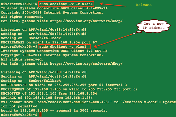
The -r flag explicitly releases the current lease, and once the lease has been released, the client exits. For example, open terminal and type the command:
$ sudo dhclient -r
Now obtain fresh IP:
$ sudo dhclient

How can I renew or release an IP in Linux for eth0?

To renew or release an IP address for the eth0 interface, enter:
$ sudo dhclient -r eth0
$ sudo dhclient eth0

In this example, I am renewing an IP address for my wireless interface:
sudo dhclient -v -r eth0
sudo dhclient -v eth0
Sample outputs:
Fig.01: Renew DHCP address example

The -v option shows information on screen about dhcp server and obtained lease.

Other options in Linux to renew dhcp

There is no need to restart network service. Above command should work with any Linux distro such as RHEL, Fedora, CentOS, Ubuntu and others. On a related note you can also try out the following commands:
# ifdown eth0
# ifup eth0
### RHEL/CentOS/Fedora specific command ###
# /etc/init.d/network restart

OR
### Debian / Ubuntu Linux specific command ###
# /etc/init.d/networking restart

nmcli command (NetworkManager) to renew IP address in Linux

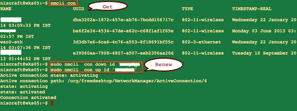
The NetworkManager daemon attempts to make networking configuration and operation as painless and automatic as possible by managing the primary network connection and other network interfaces, like Ethernet, WiFi, and Mobile Broadband devices command-line tool for controlling NetworkManager. The nmcli is a command-line tool for controlling NetworkManager and getting its status. To renew IP address using nmcli for connection named ‘nixcraft_5G’ (use ‘nmcli con‘ command to get list of all connections):
nmcli con
nmcli con down id 'nixcraft_5G'
nmcli con up id 'nixcraft_5G'
Sample outputs:
Fig.02: nmcli command in action

OSPF - Area Range Command


This tutorial shows the effect of the "area range" command in the OSPF routing process.

3 Routers for 2 OSPF areas, IPv4

If you have many small networks advertised from area 0 to any other area or from any non backbone area into the backbone, the "area range" command gives you a summary route instead of the many smaller routes. In an area the OSPF database on each router must be an exact copy of the databases of the other routers. This means, that no summarization in an area is allowed. ABRs are the only routers who can perform summarization with the help of an "area range" command.
We will then have 2 new loopback interfaces on R3 in area 10. In the OPSF configuration this interafces will be put into OSPF via the "network" statement.
R3#configure terminal
Enter configuration commands, one per line.  End with CNTL/Z.
R3(config)#interface Loopback 1
R3(config-if)#ip address 192.168.200.1 255.255.255.255
R3(config-if)#exit
R3(config)#interface Loopback 2
R3(config-if)#ip address 192.168.200.2 255.255.255.255
R3(config-if)#exit
R3(config)#router ospf 100
R3(config-router)#network 192.168.200.1 0.0.0.0 area 10
R3(config-router)#network 192.168.200.2 0.0.0.0 area 10
R3(config-router)#end
R3#
The routing table on R1 shows the two routes as hostroutes. This is normal, because loopback interfaces have the OSPF network type "Loopback" which makes the routes look as hostroutes, even if the netmask on the interface is not /32.
R1#show ip route
Codes: C - connected, S - static, R - RIP, M - mobile, B - BGP
       D - EIGRP, EX - EIGRP external, O - OSPF, IA - OSPF inter area
       N1 - OSPF NSSA external type 1, N2 - OSPF NSSA external type 2
       E1 - OSPF external type 1, E2 - OSPF external type 2
       i - IS-IS, su - IS-IS summary, L1 - IS-IS level-1, L2 - IS-IS level-2
       ia - IS-IS inter area, * - candidate default, U - per-user static route
       o - ODR, P - periodic downloaded static route

Gateway of last resort is not set

     172.17.0.0/32 is subnetted, 3 subnets
C       172.17.0.1 is directly connected, Loopback0
O IA    172.17.0.3 [110/129] via 192.168.100.2, 00:01:11, Serial1/0
O IA    172.17.0.2 [110/65] via 192.168.100.2, 00:01:11, Serial1/0
     192.168.200.0/32 is subnetted, 2 subnets
O IA    192.168.200.1 [110/129] via 192.168.100.2, 00:01:11, Serial1/0
O IA    192.168.200.2 [110/129] via 192.168.100.2, 00:00:20, Serial1/0
     192.168.100.0/30 is subnetted, 2 subnets
O IA    192.168.100.4 [110/128] via 192.168.100.2, 00:01:11, Serial1/0
C       192.168.100.0 is directly connected, Serial1/0
On R2, the Area Border Router, the "area range" command is inserted into the routing process.
R2#configure terminal
Enter configuration commands, one per line.  End with CNTL/Z.
R2(config)#router ospf 100
R2(config-router)#area 10 range 192.168.200.0 255.255.255.0
R2(config-router)#end
R2#
It reads: Take the routes from area 10 which fall into the range. Do not advertise any specific routes to the backbone, but instead advertise the summary.

R1#show ip route
Codes: C - connected, S - static, R - RIP, M - mobile, B - BGP
       D - EIGRP, EX - EIGRP external, O - OSPF, IA - OSPF inter area
       N1 - OSPF NSSA external type 1, N2 - OSPF NSSA external type 2
       E1 - OSPF external type 1, E2 - OSPF external type 2
       i - IS-IS, su - IS-IS summary, L1 - IS-IS level-1, L2 - IS-IS level-2
       ia - IS-IS inter area, * - candidate default, U - per-user static route
       o - ODR, P - periodic downloaded static route

Gateway of last resort is not set

     172.17.0.0/32 is subnetted, 3 subnets
C       172.17.0.1 is directly connected, Loopback0
O IA    172.17.0.3 [110/129] via 192.168.100.2, 00:05:00, Serial1/0
O IA    172.17.0.2 [110/65] via 192.168.100.2, 00:05:00, Serial1/0
O IA 192.168.200.0/24 [110/129] via 192.168.100.2, 00:01:45, Serial1/0
     192.168.100.0/30 is subnetted, 2 subnets
O IA    192.168.100.4 [110/128] via 192.168.100.2, 00:05:00, Serial1/0
C       192.168.100.0 is directly connected, Serial1/0
You now can see the summary route in the routing table of router R1.
On Router R2 OSPF put a new route in the routing table. The summary route can be seen as a route to NULL0 in the table.

R2#show ip route ospf
     172.17.0.0/32 is subnetted, 3 subnets
O       172.17.0.1 [110/65] via 192.168.100.1, 00:00:54, Serial1/0
O       172.17.0.3 [110/65] via 192.168.100.6, 00:00:44, Serial1/1
     192.168.200.0/24 is variably subnetted, 3 subnets, 2 masks
O       192.168.200.0/24 is a summary, 00:00:44, Null0
O       192.168.200.1/32 [110/65] via 192.168.100.6, 00:00:44, Serial1/1
O       192.168.200.2/32 [110/65] via 192.168.100.6, 00:00:44, Serial1/1


Routing table before summarization:
R2

Gateway of last resort is not set

     172.17.0.0/32 is subnetted, 3 subnets
O       172.17.0.1 [110/65] via 192.168.100.1, 00:01:08, Serial2/0
O       172.17.0.3 [110/65] via 192.168.100.6, 00:01:08, Serial2/1
C       172.17.0.2 is directly connected, Loopback0
     192.168.200.0/32 is subnetted, 2 subnets
O       192.168.200.1 [110/65] via 192.168.100.6, 00:01:08, Serial2/1
O       192.168.200.2 [110/65] via 192.168.100.6, 00:01:08, Serial2/1
     192.168.100.0/30 is subnetted, 2 subnets
C       192.168.100.4 is directly connected, Serial2/1
C       192.168.100.0 is directly connected, Serial2/0


R1

Gateway of last resort is not set

     172.17.0.0/32 is subnetted, 3 subnets
C       172.17.0.1 is directly connected, Loopback0
O IA    172.17.0.3 [110/129] via 192.168.100.2, 02:00:13, Serial2/0
O IA    172.17.0.2 [110/65] via 192.168.100.2, 02:00:13, Serial2/0
     192.168.200.0/32 is subnetted, 2 subnets
O IA    192.168.200.1 [110/129] via 192.168.100.2, 00:00:07, Serial2/0
O IA    192.168.200.2 [110/129] via 192.168.100.2, 00:00:07, Serial2/0
     192.168.100.0/30 is subnetted, 2 subnets
O IA    192.168.100.4 [110/128] via 192.168.100.2, 02:00:13, Serial2/0
C       192.168.100.0 is directly connected, Serial2/0


R3

Gateway of last resort is not set

     172.17.0.0/32 is subnetted, 3 subnets
O IA    172.17.0.1 [110/129] via 192.168.100.5, 02:04:59, Serial2/1
C       172.17.0.3 is directly connected, Loopback0
O       172.17.0.2 [110/65] via 192.168.100.5, 02:04:59, Serial2/1
     192.168.200.0/32 is subnetted, 2 subnets
C       192.168.200.1 is directly connected, Loopback1
C       192.168.200.2 is directly connected, Loopback2
     192.168.100.0/30 is subnetted, 2 subnets
C       192.168.100.4 is directly connected, Serial2/1
O IA    192.168.100.0 [110/128] via 192.168.100.5, 02:05:00, Serial2/1


Routing table after summarization:

R2

Gateway of last resort is not set

     172.17.0.0/32 is subnetted, 3 subnets
O       172.17.0.1 [110/65] via 192.168.100.1, 00:00:03, Serial2/0
O       172.17.0.3 [110/65] via 192.168.100.6, 00:00:03, Serial2/1
C       172.17.0.2 is directly connected, Loopback0
     192.168.200.0/24 is variably subnetted, 3 subnets, 2 masks
O       192.168.200.0/24 is a summary, 00:00:03, Null0
O       192.168.200.1/32 [110/65] via 192.168.100.6, 00:00:03, Serial2/1
O       192.168.200.2/32 [110/65] via 192.168.100.6, 00:00:03, Ser
     192.168.100.0/30 is subnetted, 2 subnets
C       192.168.100.4 is directly connected, Serial2/1
C       192.168.100.0 is directly connected, Serial2/0

R1

Gateway of last resort is not set

     172.17.0.0/32 is subnetted, 3 subnets
C       172.17.0.1 is directly connected, Loopback0
O IA    172.17.0.3 [110/129] via 192.168.100.2, 02:04:42, Serial2/0
O IA    172.17.0.2 [110/65] via 192.168.100.2, 02:04:42, Serial2/0
O IA 192.168.200.0/24 [110/129] via 192.168.100.2, 00:01:08, Serial2/0
     192.168.100.0/30 is subnetted, 2 subnets
O IA    192.168.100.4 [110/128] via 192.168.100.2, 02:04:42, Serial2/0
C       192.168.100.0 is directly connected, Serial2/0


R3

Gateway of last resort is not set

     172.17.0.0/32 is subnetted, 3 subnets
O IA    172.17.0.1 [110/129] via 192.168.100.5, 02:02:35, Serial2/1
C       172.17.0.3 is directly connected, Loopback0
O       172.17.0.2 [110/65] via 192.168.100.5, 02:02:35, Serial2/1
     192.168.200.0/32 is subnetted, 2 subnets
C       192.168.200.1 is directly connected, Loopback1
C       192.168.200.2 is directly connected, Loopback2
     192.168.100.0/30 is subnetted, 2 subnets
C       192.168.100.4 is directly connected, Serial2/1
O IA    192.168.100.0 [110/128] via 192.168.100.5, 02:02:37, Serial2/1


Wednesday, March 30, 2016

VMware VM files

What are the VM files consist of?


https://www.youtube.com/watch?v=J7-nAw4W0mY

Friday, March 4, 2016

ESXi 6 file upload error: "failed to log into nfc server" or "failed to create session to with username and password with length" during upload of file to a datastore

During upload of file to a ESXi 6 datastore the following errors are triggered:

When using vSphere client for windows, the error "failed to log into nfc server"


OR

When using vSphere Web Client, the error "failed to create session to with username and password with length"


Solution:


Client does not sit on the same network as the ESX server.  In order to upload files using the Datastore Browser port 902 has to be opened between the client and the server.
Also, check other network related configuration between the ESXi host , vCenter and the system running the vSphere Windows or Web client 


Thursday, March 3, 2016

Deploying the vCenter Applicance (vCSA) in vSphere 6 Environement


  • Check the DNS and reverse pointers are operational.

Add a host record for the vCenter appliance.


Add a reverse pointer record for the vCenter appliance.


Perform a NSLOOKUP command to check DNS name resolution of the vCenter server.

NSLOOKUP <name of vCenter server>


  • From a deployment workstation, install the Client Integration Plug-in and launch vcsa-setup.html to deploy the vCenter appliance to a ESXi host.

From VMWare, download the ISO named VMware-VCSA-all-6.0.0-3343019.iso and mount it on your deployment workstation using free tool such as WinCDEMU.

ESXi 6 and vCenter download here.  


Navigate to the folder containing the Client Integration Plug-in and install the plug-in.


Navigate to the folder containing the vcsa-setup.html and launch it  to initiate the vCenter server install.


Specify the ESXi host to deploy the vCenter appliance.


For security, compare the thumbprint with the selected ESXi host.  Once comfirmed, click YES


Specify the vCenter server appliance to be deployed


Platform service controller can be install as embedded for smaller deployments or as a external controller for larger deployments.


Create a new SSO domain.
Note: SSO Domain name must be different than your Windows AD domain.


Specify the appliance size.
Note: Ensure that the ESXi host that will be running the vCSA meets the system requirements.  For example, Tiny requires 2vCPU and 8G of RAM on the ESXi host.


Specify the destination datastore for the vCSA and enable Thin Disk Mode to save storage space.


Specify the database type.  Embedded requires no configuration.  Available Oracle database is required for latter option.


Specify the network settings for the vCSA.


Synchronize the time to ensure SSO, certificate and logging works.
Enable SSH.


Summary of the installation.


Downloading and deploying vCSA.

Once complete, log onto the vSphere Web Client via the URL https://your_vCSA_name/vsphere-client as administrator@vsphere.local


vCSA SSO sign-on.

Done!


If above method results in vCSA not working , try importing or deploying the vCSA via the OVA template.


Copy and rename the vmware-vcsa to vmware-vcsa.ova


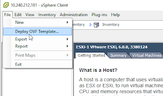
Connect to the ESXi host via Windows or Web vSphere client.


Specify the vCSA OVA file.


Note: Ensure that you do not power on after deployment!


Browse to the host's datastore to access the vmx file of the vCSA VM and download to modify.


Add the following entries to the vCSA VMX file:

guestinfo.cis.appliance.net.addr.family = "ipv4"
guestinfo.cis.appliance.net.mode = "static"
guestinfo.cis.appliance.net.addr = "IP address of vCSA server"
guestinfo.cis.appliance.net.prefix = "23"
guestinfo.cis.appliance.net.gateway = "IP address of your gateway"
guestinfo.cis.appliance.net.dns.servers = "IP address of your AD DNS server"
guestinfo.cis.vmdir.password = "password of adminstrator@vsphere.local"
guestinfo.cis.appliance.root.passwd = "password of adminstrator@vsphere.local"


Once vCSA VMX file has been updated, upload it to the datastore.


Power on the vCSA VM


Verify the network settings. vCSA should work now.

Tuesday, March 1, 2016

Web Interface for ESXi without vCenter


Hmm....OK....I downloaded the ESXi 6 Hypervisor and installed it in VMWare Workstation 11.  ( You can download the trial here.  You may have to register with VMWare if you already have not.  https://my.vmware.com/en/web/vmware/info/slug/datacenter_cloud_infrastructure/vmware_vsphere/6_0)

Now, how do I access the web based user interface to manage the standalone ESXi host?

It’s now possible to manage standalone ESXi hosts with not only the Windows vSphere Client or vCenter, but with a web interface for ESXi 


Installing it over the Internet

  1. Enable SSH.  (In DCUI, Press F2 -Customize System/View Logs ->Troubleshooting Options->Enable SSH)
  2. SSH into your ESXi host
  3. Run the command


Installing it from a local file
  1. Download the VIB file
  2. SSH into your ESXi host
  3. Copy the VIB file to /tmp/
  4. Run the command

    Making sure you include the full path name to the file or else installation will fail
If the VIB installation completes successfully, you should now be able to navigate a web browser to https://<esxip>/ui and the login page should be displayed.
Capture2
Login with your usually ESXi credentials and try it out.
running